Table of Contents
RRT
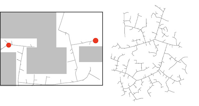
As a first experiment during the course, I looked into tree structures used in computer science, and implemented a Rapidly-exploring random tree (RRT) http://en.wikipedia.org/wiki/Rapidly-exploring_random_tree. This algorithm fills a space with a tree where random points are connected incrementally to their closest neighbor. RRTs are commonly used in robotics as a tool for path planning.
The idea was to fill shapes with a tree like structure:
I then made some experiments with growing the tree interactively by letting the user click to add new branching points. The branches of the tree are visualized by interpolating a particle along a qadratic bezier curve with a random control point.
Sqr Root
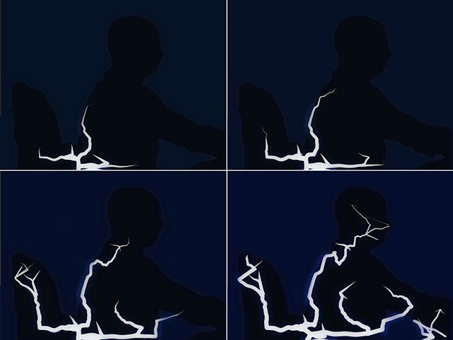
At the same time I was working on a prototype for a interactive work together with some algorithms to extract meaningful data from live video input. I then decided to attempt building a software that would animate a tree structure, which would react in real time to video input, allowing people to play with digital tree structures in an interactive installation. Basically the program examines video and through blob detection, a common technique from computer vision, extracts polygonal silhouettes from pixels in a given brightness range. These polygons are then fed to an algorithm that extracts a skeletal structure, which every frame determines that path for the digital tree to grow.
My visual inspiration were the leafless trees that I was seeing every day biking back and forth from Scheveningen. Seen against the sky at different times of the day they create some beautiful images.
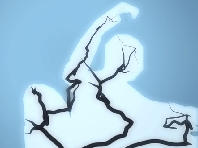
Here are some screenshots of a prototype of the software running:
Although initially using raw video ( movies or a webcam ) as a source, I ended up using the Microsoft Kinect as a sensor. The kinect is a motion sensing device by Microsoft which provides an image of the scene as a normal camera, but calculates for each pixel a depth value. This allows to easily distinguish different objects in it’s view. There's also open source software available ( OpenNI / NITE ) which is able to precisely track the orientations of the human body. I decided not to use it because it only works with human forms and needs a initial recognizable pose to start tracking ( I think newer versions of the software don’t require the initial pose ). I also wanted to test and develop a skeletonization algorithm I have been working on the is described in the following section.
Constrained Delaunay Triangulation Skeleton ( CDT Skeleton )
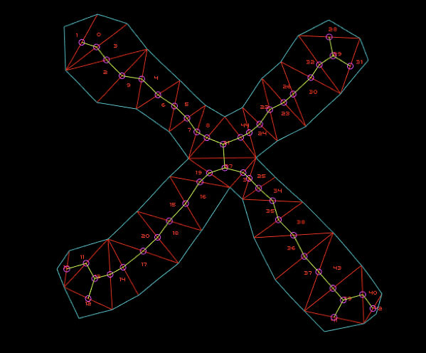
When seeing a form, it’s easy for us to imagine it’s structural skeleton, but this is not a trivial task for a computer. There are several methods from computational geometry to extract a skeletal structure from a shape, the most common being Morphological thinning, the Medial Axis Transform and the Straight Skeleton. I had already started working on a simple system to extract a skeleton out of a polygon based on it’s triangulation. A Delaunay Triangulation is a triangulation of a set of points where circumscribing circle of any facet of the triangulation contains no vertex in its interior ( wiki ). In the case of a Constrained Delaunay Triangulation, segments can be forced to be part of the triangulation allowing to correctly triangulate complex polygons. A graph that approximates the medial axis of the polygon can be built by joining adjacent triangles. The algorithm to build such graph works as follows:
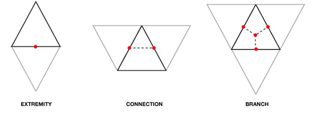
In a first pass each triangle is classified based on it’s number of neighbors.
| # Neighbors | Type |
|---|---|
| 1 | Extremity |
| 2 | Connection |
| 3 | Branch |
The type of the triangle determines where the edges of the skeleton are connected: For each extremity triangle, a vertex is added to the graph at the mid point of the neighboring triangle edge. For connection triangles, vertices are added at the midpoints of neighboring edges. For branch triangles, a vertex is added at the centroid
This method is simple and very fast, making it ideal for a real time application and turned out to work well for this use case. I came up with this system because it seemed as the quickest and simplest way of building a skeleton out of a shape, and thought it was a hacky work-around not implementing more complex skeletonization algorithms. It turns out that there are a couple papers describing pretty much the same method, although it is not widely used in the scientific community because of it’s strong dependance on the triangulation method used. ( TODO: linkies )
Matching the tree with the skeleton
The tree structure is built by nodes called atoms which are inserted by iterating over the skeleton beginning from the bottom. Each atom is then connected to the nearest neighbor which is already part of the tree. This is very similar to the way a RRT is built. The CDT Skeleton is very sensible to variations in roughness of the shape. The camera input is noisy and the number of vertices and order of blobs is different each frame; thus it is a challange to track and smoothly animate points along the skeleton. To smooth the animations of the tree over consecutive frames, each atom is assigned a best matching target node of the skeleton, and interpolates towards it’s new position using a mass-spring function. If no optimal match is found for a adjustable time period, the atom and all it’s children are pruned from the tree. In order to create a more ‘tree like’ image, an atom is always inserted as a starting point at the lower middle of the frame.
( TODO: illustrations )
